

Technical · 6 min read
Guide pillars get a mold base close; interlocks make it repeat
Two alignment systems, one of which has to slide. When a cosmetic shut-off or a curved parting line needs tighter registration than a guide fit allows, the drawing has to name the interlock, the datum and who checks the contact.
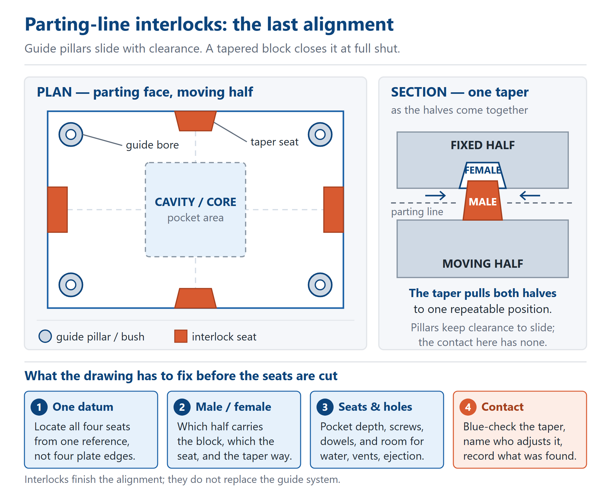
A mold base has two alignment systems, and only one has to slide. Guide pillars and bushes bring the fixed and moving halves together over the whole opening stroke, so they are made with clearance — that is what lets a lubricated steel pillar run in a bush without seizing. It also means the halves can sit a little differently each time they close. For a flat parting face that is fine; for a cosmetic shut-off or a curved parting line, that difference shows up as a witness line or flash. A parting-line interlock takes out the last freedom at full shut.
The word interlock covers several parts, so name the one. A tapered interlock is a male block with angled flanks on one half and a matching female seat in the other; as the press closes, the wedge pulls both halves into one repeatable position. Straight-sided side locks locate one axis and carry side load but do not centre both axes. Each wants a different pocket, screw pattern and fitting operation. A drawing that says only “fit interlocks” leaves the choice to the shop, and the consequence shows up at the press.
Guide pillars stay in charge of travel. An interlock should engage only in the final part of the close; it must not bottom before the parting faces meet. If the taper bottoms first, clamp force goes into the block instead of the shut-off, giving flash and a bruised taper face. Seat height, pocket depth and shut height therefore belong on the same drawing — where the base meets the press lists the interfaces this height must agree with.
Clearance is also a temperature question. Two halves at different temperatures do not grow by the same amount, so a fit comfortable cold can bind hot — cold fit, hot bind explains the mechanism for guide bores. Interlocks add a second constraint: tight tapers across a wide plate leave thermal growth nowhere to go. Say which half is fixed, whether the other floats, and what temperature split the tool is designed around. That is a design decision.
Then there is the space. The parting face is the most crowded surface on a mold base. An interlock needs a pocket in both halves, counterbores, tapped holes and dowel holes; all of that competes with cooling ports and O-ring seats, ejector holes, vent lands, slide seats, and the screws and dowels holding the plates together. Put interlock positions on the first layout, before those pockets are programmed. Moving one afterwards means moving two others.
Locate every seat from one reference, the same datum the guide bores and cavity pocket use — not four convenient plate edges. Clamping datum and flatness sets out why one reference governs the stack. A taper can be cut perfectly and still locate the halves wrongly if the male pockets were measured from one corner and the female pockets from another: the blocks touch, but hold the tool in a repeatable wrong position, harder to diagnose than a plain offset. A second mold base must inherit that datum.
Which half carries the male block is a design decision. It affects how the halves are handled and stored, whether the tool can be assembled a hundred and eighty degrees out, and whether the arrangement is deliberately handed so a mistake is impossible. Show it in a view, not a note, and give the seats a letter the assembly sheet can refer to. One mold base, three parties is why this gets lost: the designer draws the lock, the toolmaker fits it, our shop cuts the seats. One revision covers all three.
The seats are machined work; the blocks are usually bought-in hardware. Write down who supplies them — a standard set with maker and part number, or blocks made to your detail — and which holes we cut: pocket depth, counterbore diameter and depth, thread standard, dowel position. Dowels locate, screws clamp separates the hole families, and depth, not diameter explains why a shallow counterbore loads the screw head. A lock held by a bottoming screw moves.
Contact is an assembly result, not a dimension you inspect on a plate. The taper is blued, the halves closed, the contact pattern read; adjustment is made by grinding or shimming the seat, not by pulling the screws tighter. Too tight holds the parting line open, too loose does nothing. Name who fits, who signs off, and what record ships — what an inspection record proves is the same argument for measured values. If the check fails, that is a disposition decision with a written owner (concession, rework or remake). Our own callout for fitting and ground faces is ±0.02 mm and Ra 0.8 µm; these are our figures, not a claim of compliance with a general standard.
The symptoms read backwards once you know them. A witness line stepping across a cosmetic face, flash on one side only, one flank of a taper polished bright while the other stays dull, a mold that resists the last part of the close, or a core sitting off centre once the tool is warm — each points at the interlock detail before the cavity. Curved parting lines make it sharper, because the contact band is no longer one plane.
For buyers sourcing a mold base from China, this is a document problem before it is a machining problem. Chinese mold base suppliers can cut a perfectly dimensioned seat and still leave the mating block, the contact check and the adjustment unassigned, because those decisions were never written down. Put who-supplies, who-fits and who-records on the plate list, and ask for the contact-check record in the crate. Our shop in Dongguan, China works to written detail — one practical part of what buying a mold base from China actually involves. Distance adds no party; it removes the chance to settle a question at the bench.
Eight lines settle most interlock enquiries.
1. Type: tapered, straight-sided or round pin, with maker and part number or a detail.
2. Which half carries the male and which the female, shown in a view.
3. Seat positions from one datum, shared with guide bores and cavity pocket.
4. Pocket and seat depth, so the taper cannot bottom before the faces meet.
5. Screw and dowel callouts, with the thread standard used elsewhere.
6. Which half is fixed, whether the other floats, the temperature split.
7. Contact requirement, who blues and adjusts, who signs off, what record ships.
8. Drawing number, revision letter, named owner of the detail. What to send with an RFQ covers the rest.
Interlock seats are ordinary work here, cut on the same setup as the guide bores and cavity pockets for a standard plastic mold base, an injection mold base, a precision ground base or a custom non-standard base. Send the layout with the datum, both halves and the contact requirement marked. Ordinary mold bases from our Dongguan, China mold base lines usually ship in 7–10 days; capacity is 2,000+ sets and pieces per month; and you deal directly with the factory that machined the seats.
Related